Part location
Find the X and Y position of components on a conveyor, fixture, pallet or presentation area.
Give robots reliable position and orientation data for picking, placing, loading or processing components that do not arrive in one fixed location.
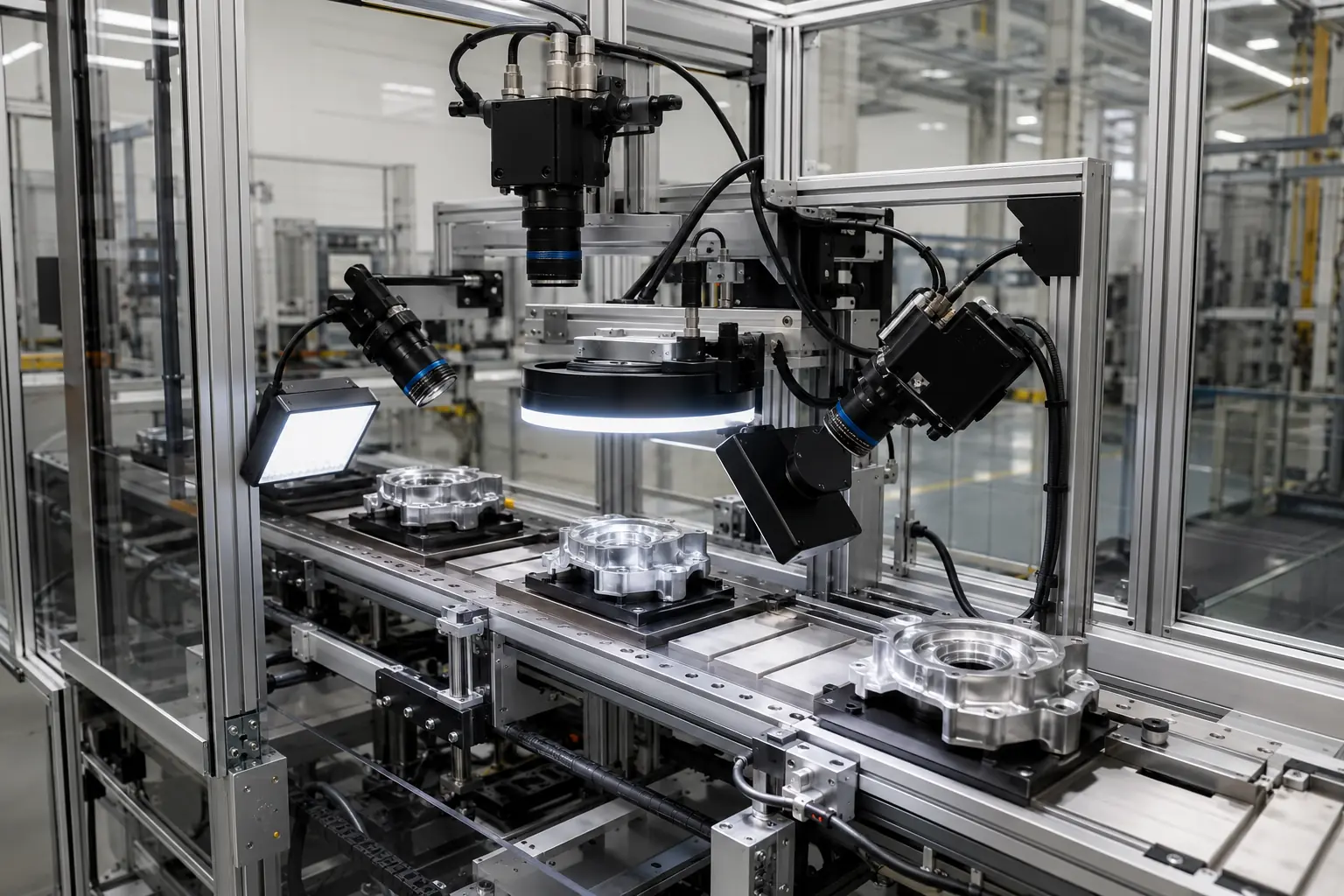 Application-led imaging Proved with the real product, defect and line conditions.
A calibrated vision system finds a product or feature in camera coordinates, converts that result into the robot or machine coordinate system, and sends position and angle data to the automation controller. A second check can confirm the pick, placement or completed operation.
Every check is confirmed against the real product, defect set, line speed and production environment before final specification.
Find the X and Y position of components on a conveyor, fixture, pallet or presentation area.
Return rotation or key feature direction so the robot approaches the component correctly.
Use 2D for stable height applications or consider depth data when pose and height vary.
Confirm that a component was acquired, removed or transferred before the next robot move.
Check location, orientation, seating or presence after assembly, loading or packing.
Read a code or recognise a part family so automation applies the correct operation.
Part contrast, overlap and occlusion, height variation, calibration stability, conveyor motion, robot accuracy, gripper access, cycle time, field of view and the recovery method when no valid target is found.
The complete solution can include cameras, lighting, calibration, robot communications, PLC handshakes, target prioritisation and post-process inspection. The interface and fault states are agreed with the automation team before commissioning.
Vision cannot compensate for an unsuitable gripper, unstable mechanics or a feature hidden from every practical view. Accuracy is a property of the complete calibrated system and is confirmed under production conditions.
Use these related pages to compare the inspection methods and production environments that may form part of the project.
2D guidance is often suitable when the working height is controlled and the robot only needs planar position and rotation. Variable height or full pose may require 3D sensing.
Yes, where encoder tracking, timing, robot capability and product spacing support conveyor tracking. The full cycle must be proved at the required line rate.
Accuracy depends on image resolution, calibration, working distance, mechanics, robot repeatability and the feature being located. We define and test the complete tolerance stack.
Sometimes. A separate view is used when the guidance angle cannot clearly prove the final assembly or when inspection needs different lighting or resolution.
Send us samples, images, line-speed information and the defects you need to detect. We’ll recommend the right next step.