Height and depth
Measure steps, recesses, protrusions and component seating against agreed limits.
Measure shape as well as appearance. We integrate 3D sensors, product handling, inspection software and the line response around the feature that must be controlled.
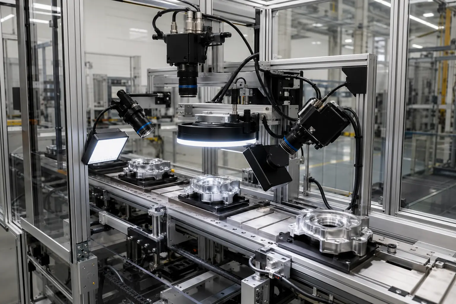 Application-led design Proved against the real product, defect and production conditions.
Use 3D inspection when the pass/fail decision depends on height, depth, profile, flatness, volume or surface geometry that a conventional 2D image cannot prove reliably. The sensing method is selected after the required measurement range, smallest defect, material, speed and product presentation are understood.
Each requirement is tested against representative products, normal variation, line speed and the agreed production response.
Measure steps, recesses, protrusions and component seating against agreed limits.
Inspect visible gaps, offsets and relative surface positions in assemblies.
Compare cross-sections, edges, beads and formed profiles with an approved tolerance window.
Identify out-of-plane variation where the field of view and sensor resolution support the requirement.
Calculate geometry-derived area or volume for presented products and deposited materials.
Detect agreed dents, raised material, chips or deformation that may be difficult to separate by colour alone.
Laser profiling, structured light, stereo and other 3D methods have different accuracy, speed, working-distance and surface limitations.
Gloss, transparency, very dark surfaces, vibration and steep edges can affect the returned height data and must be tested on real samples.
Calibration, product tracking, recipe control, reject timing and retained results determine whether the measurement becomes a dependable production control.
The useful result is a repeatable decision that operators can understand and the production line can act on.
State the feature, tolerance, field of view and smallest unacceptable variation.
Test good, failed and borderline samples across normal material and finish variation.
Challenge speed, vibration, presentation, calibration and environmental influences.
Connect recipes, tracking and response, then test against agreed production evidence.
A 2D camera is often the simplest choice for position, colour, print and visible edge checks. A 3D sensor adds measured height or profile information when contrast alone is ambiguous. Some applications benefit from both: 2D verifies appearance and identity while 3D proves geometry.
2D vision evaluates image position, shape, colour and contrast in a flat image. 3D vision adds height or depth data, allowing geometry such as steps, profiles, volume and warpage to be measured.
Often, but performance depends on the sensor method, angle, finish and required resolution. Representative samples must be tested before the architecture is fixed.
Yes, when acquisition and processing fit the line cycle and product movement is controlled. Speed, vibration and trigger repeatability are part of the feasibility test.
Frequently, subject to working distance, access, guarding, product presentation and available reject or stop distance. A line survey confirms the practical constraints.
Accuracy is application-specific and depends on sensor resolution, measurement range, calibration, surface behaviour, mounting stability and environment. It should be stated and proved against the real feature and tolerance.
Send samples, images, line-speed information and the defects you need to detect. We’ll recommend the right next step.